


Hi,
Below is a suggestion to improve the performance of a standard Keppe motor. Certainly there are better ways to do so but what is described below is an easy and cheap way to do so.
Normally, this should work but no guarantees !
Prior to posting this I asked the administrator and ms Stein if they would have any objections. There were no responses for more than a week so I presume it's OK.
Required materials (extras compared to basecase)
Procedure
You’ll have to install a set of supports for 4 switches in 2 pairs and connect them to the rectifier and the capacitor.

All components are ready now, you only have to connect them as listed in the table and shown on the schematic:
Components:
Table:

Notes
How does it work ?
The motor generates an AC voltage. Via the rectifier, that AC is converted to DC and used to charge the capacitor. When the switches B1 and B2 are closed, the capacitor acts as a battery for the motor and is (partially) discharged.
Typical osciloscope picture:
Note: voltage peaks omitted for clarity
Disadvantage of this set-up :
Switches A1 and A2 (and similarly B1 and B2) should open and close simultaneously but they don’t. The current can only flow when both are closed. Normally, the switches each close during 45 to 60° of the magnets’ rotation on the motor shaft. Since with this layout the switches are 10 to 15° apart, they are closed only some 15 to 30° together so less energy can be fed to the motor (energy = volts x current x time and with this setup there is less time).
You can overcome this by one of the following methods:
Try it yourself and post your results.
Below is a suggestion to improve the performance of a standard Keppe motor. Certainly there are better ways to do so but what is described below is an easy and cheap way to do so.
Normally, this should work but no guarantees !
Prior to posting this I asked the administrator and ms Stein if they would have any objections. There were no responses for more than a week so I presume it's OK.
Required materials (extras compared to basecase)
- 3 reed switches
- capacitor (advise: at least 47 µF, I used a 220 µF one, suitable for at least 250 V peak voltage). Both AC and DC capacitors are OK.
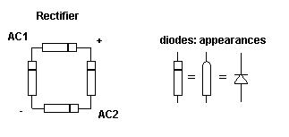
- rectifier bridge or 4 diodes, suitable for at least 250V peak voltage
- 1 switch (single pole), similar to the one that is already on your motor
- connectors (I use terminal blocks)
- wires
- wood or cardboard
- glue / tape
Procedure
You’ll have to install a set of supports for 4 switches in 2 pairs and connect them to the rectifier and the capacitor.
- Disconnect the reed switch
- Remove it from its’ support
- Remove the old support.
- Construct the new supports.
It is easy to make one from cardboard but you can also use any other material. Enclosed picture shows how you could make cardboard supports.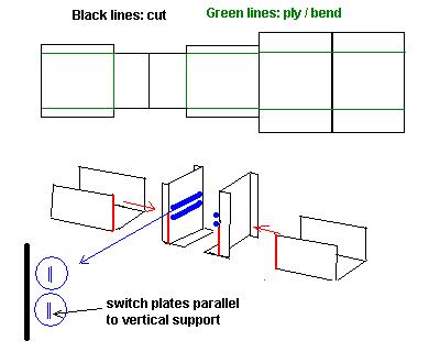
- Attach the switches to the supports. To allow easy adjustments of the switches later on, use tape instead of glue. The plates of the switch best are aligned as on the sketch (parallel to the support).
If there is not sufficient space between the motor frame and the ends of the reed switches, you can bend the switch ends (be careful is you do that, the reed switches are quite vulnerable). - Position the support frames on the system baseplate. The alignment procedure is alike in the motor manual. Test the positioning by turning the motor shaft; when the small magnet passes along a set of switches, you should hear 2 clicks. If not, adjust the position of the support.
If there is not sufficient place on the system baseplate, you’ll have to relocate the switch and the battery support or just use a larger baseplate - Construction of the rectifier (if you have bought an of the shelve rectifier bridge, you can skip this step). Quite easy: connect the 4 diodes as per attached schematic.
All components are ready now, you only have to connect them as listed in the table and shown on the schematic:
Components:
- Switch 1 (power supply)
- Switch 2 (booster)
- Motor
- Reed switches A1, A2, B1 and B2
- Rectifier
- Capacitor
- Battery
- Node X
- Node Y
Table:
| From | To | °°°°° | From | To |
| Battery + | Switch 1 b | | Switch 1 a | A1a |
| A1b | X | | Battery - | A2a |
| A2b | Y | | Y | Motor b |
| Motor a | X | | X | Rectifier AC1 |
| X | B1a | | B1b | Capacitor - |
| Capacitor - | Rectifier - | | Capacitor + | Switch 2a |
| Switch 2a | Rectifier + | | Switch 2b | B2b |
| B2a | Y | | Y | Rectifier AC2 |
Notes
- When you use a DC capacitor mind the polarity, if you connect it wrong the capacitor may blow up !
- Reed switch A2 is not really needed in this set-up but it is better to install it anyway.
- If you close Switch 2 the booster will start and you should see / hear an increase in motor rpm.
- In case of doubts, the schematic is ruling over the table.
How does it work ?
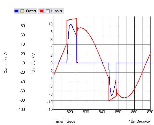
The motor generates an AC voltage. Via the rectifier, that AC is converted to DC and used to charge the capacitor. When the switches B1 and B2 are closed, the capacitor acts as a battery for the motor and is (partially) discharged.
Typical osciloscope picture:
Note: voltage peaks omitted for clarity
Disadvantage of this set-up :
Switches A1 and A2 (and similarly B1 and B2) should open and close simultaneously but they don’t. The current can only flow when both are closed. Normally, the switches each close during 45 to 60° of the magnets’ rotation on the motor shaft. Since with this layout the switches are 10 to 15° apart, they are closed only some 15 to 30° together so less energy can be fed to the motor (energy = volts x current x time and with this setup there is less time).
You can overcome this by one of the following methods:
- Change to electronic switching circuits (e.g. sensor to detect magnet and circuit to open and close switches)
- Add an extra switching magnet to the other shaft end and install half of the switches over there. This is the setup I use now: switches A1 and B1 are at one shaft end and A2 and B2 at the other end. The switching magnets have to be carefully aligned with each other.
Try it yourself and post your results.


