


Hi all,
I would like suggest to post the test results of your motors under this topic so that we can learn from each other.
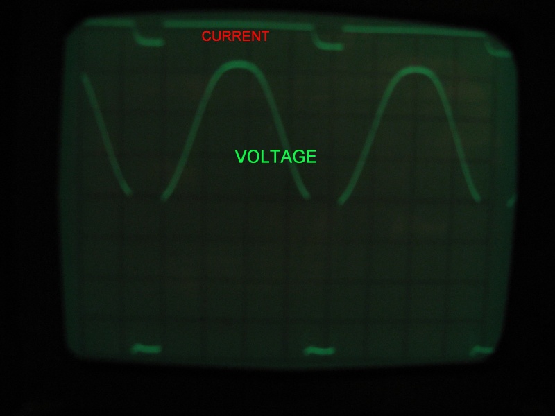
As an example, enclosed I post an oscilloscope picture of my motor's coil current and voltage readings.
* The current is always zero, except when the reed swich closes.
* The voltage varies according a sinus function and drops almost to zero when the switch closes.
* Timescale: 10 msec per division (so one cycle = +/- 42 msec which means motor rpm = +/-1430).
Note: this motor deviates from the Keppe manual so your own motor readings certainly will be different.
Hope to see soon some of your data.
I would like suggest to post the test results of your motors under this topic so that we can learn from each other.
As an example, enclosed I post an oscilloscope picture of my motor's coil current and voltage readings.
* The current is always zero, except when the reed swich closes.
* The voltage varies according a sinus function and drops almost to zero when the switch closes.
* Timescale: 10 msec per division (so one cycle = +/- 42 msec which means motor rpm = +/-1430).
Note: this motor deviates from the Keppe manual so your own motor readings certainly will be different.
Hope to see soon some of your data.


 [url][/url]
